
Muscle Car
Using EMG signals to drive a remote-controlled car, because we can. Lol.
What Is This Silliness?
Surface EMG electrodes on the forearm and bicep pick up muscle electrical signals in the µV–mV range. An analog processing chain amplifies, filters, rectifies, and thresholds these signals into digital trigger pulses. An ESP32S3 microcontroller debounces those pulses and fires transistors soldered directly across the buttons of a hacked RC car transmitter.
Three muscles, four actions. Bringing a ridiculous new meaning to “Muscle Car.”
✓ Fully Working BEE 533 · Final Project| Signal Source | Surface EMG, forearm & bicep |
| Electrodes | Floating hydrogel foam pads, 3 per channel |
| Amplifier | INA333 IC (or 3× LM358), Gain = 1000 |
| Filter | Active band-pass, 10–500 Hz, unity gain |
| Rectifier | Precision full-wave, 2× LM358 |
| Comparator | Non-inverting, Vref = 0.5V |
| Microcontroller | ESP32S3, signal debounce & car control |
| Transmitter | 2.4GHz RC TX, buttons hacked with 2N3904 BJTs |
| Channels | 3 (Left, Right, Forward) — Reverse = Left+Right |
The Signal Chain
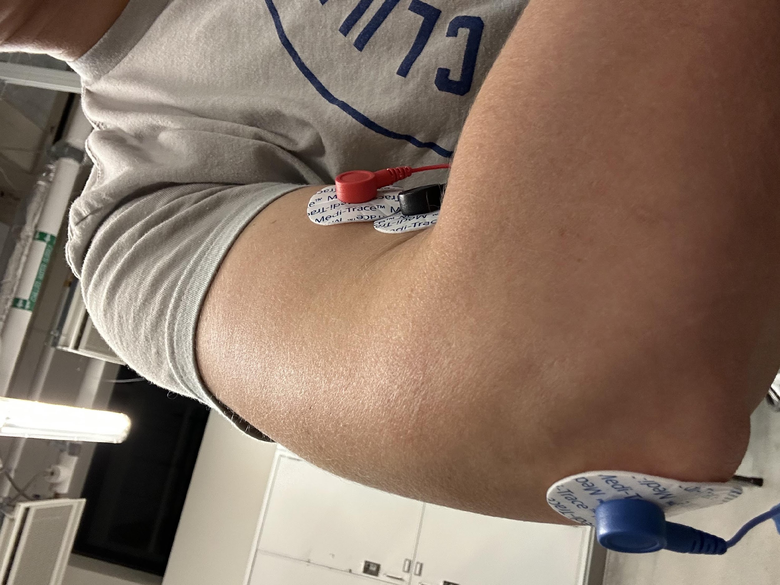
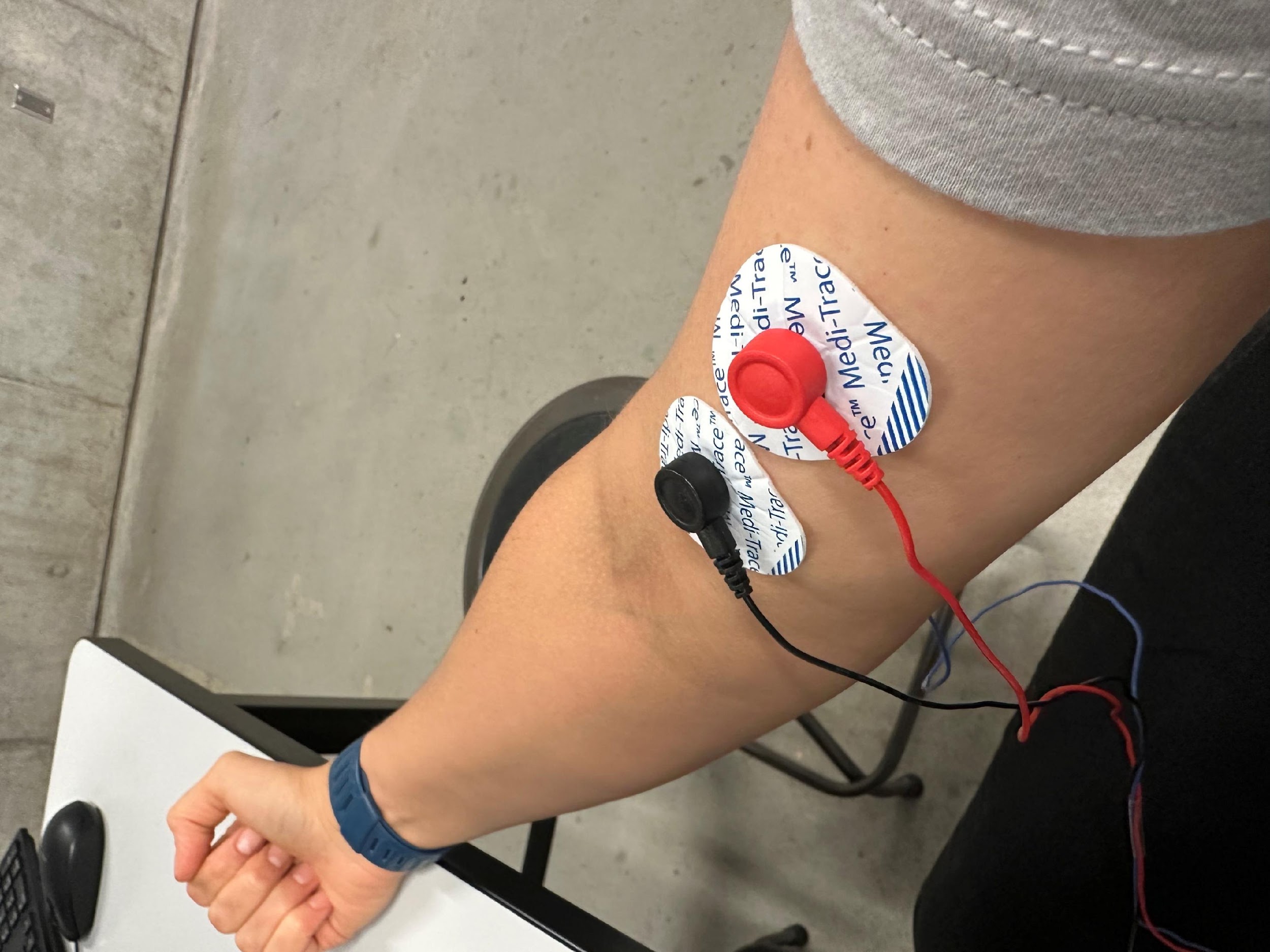
Signal Detection & Electrodes
Floating electrodes with disposable hydrogel foam pads pick up signals from the forearm and bicep. The electrodes don’t contact skin directly (the gel pad does), which reduces motion artifacts significantly. Two signal electrodes are placed within 2cm of each other along the muscle’s length; a third ground electrode sits on a bony reference surface like the elbow, or in the case of hastily-made test videos, held in the mouth briefly.
Three channels run in parallel, one per car action, with a fourth action triggered by two channels simultaneously triggered. In a single-person configuration the ground electrodes can be consolidated to one.
Instrumentation Amplifier — Gain = 1000
Two designs were built and compared. The discrete design uses three LM358 op-amps: a first stage at gain 50 and a second differential stage at gain 20, for a total of 1000. Input diodes on each signal line provide patient protection.
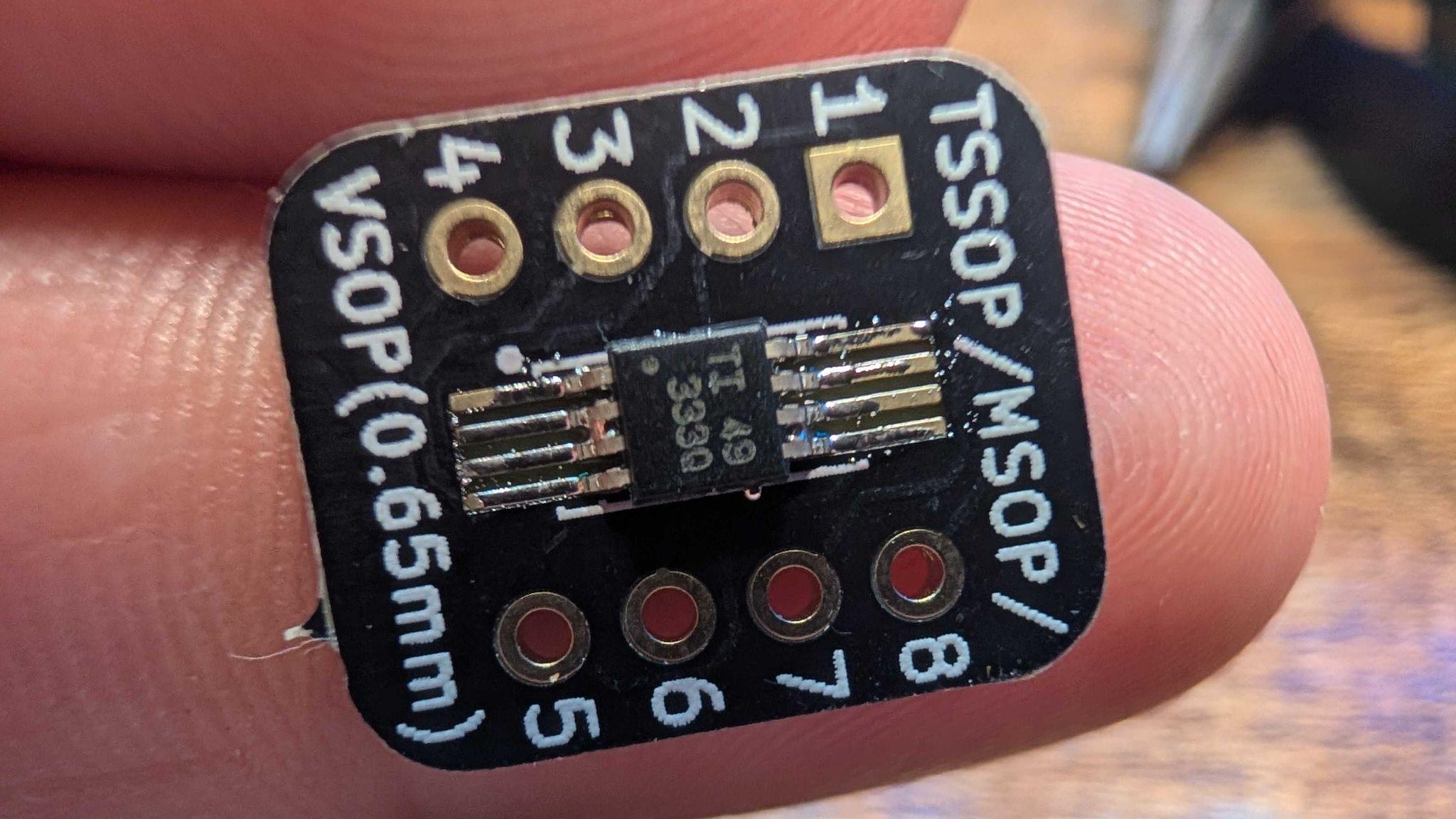
The second design uses an INA333 IC, which is a single-chip instrumentation amplifier set by one gain resistor, with internal RFI filtering and a worst-case offset of only 25µV versus 3mV for the LM358. Its lower supply voltage (1.8–5.5V) also meant the output was already in the ESP32S3’s acceptable range with no voltage divider needed. This approach would be better suited to pick-and-place PCB mounting, as hand-soldering proved particularly tricky on such a small IC.
Band-Pass Filter — 10 to 500 Hz
An active second-order band-pass filter eliminates DC drift and high-frequency noise outside the dominant EMG band. Designed with unity gain. Low cutoff at 10Hz (fc1 = 1/(2π·33k·0.47µF)), high cutoff at 500Hz (fc2 = 1/(2π·33k·10nF)).
Precision Full-Wave Rectifier
EMG signals are bipolar: the band-pass output swings positive and negative. A precision two op-amp full-wave rectifier folds the negative half up, preserving all signal energy above zero. Standard diode bridges were tried first but produced half-wave behavior when driven single-ended. The two op-amp design worked after removing pull-down resistors on the non-inverting terminals that were causing an unintended DC offset.
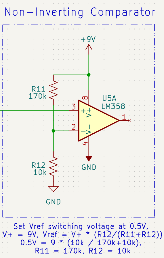
Comparator — Trigger at 0.5V
A non-inverting comparator with Vref = 0.5V converts the rectified EMG envelope into a clean digital trigger: high when the muscle fires, low when it doesn’t. Vref is set by a resistor divider (R11 = 170kΩ, R12 = 10kΩ) from the 9V rail. Output is stepped down to ~3.7V by a voltage divider before reaching the ESP32S3.
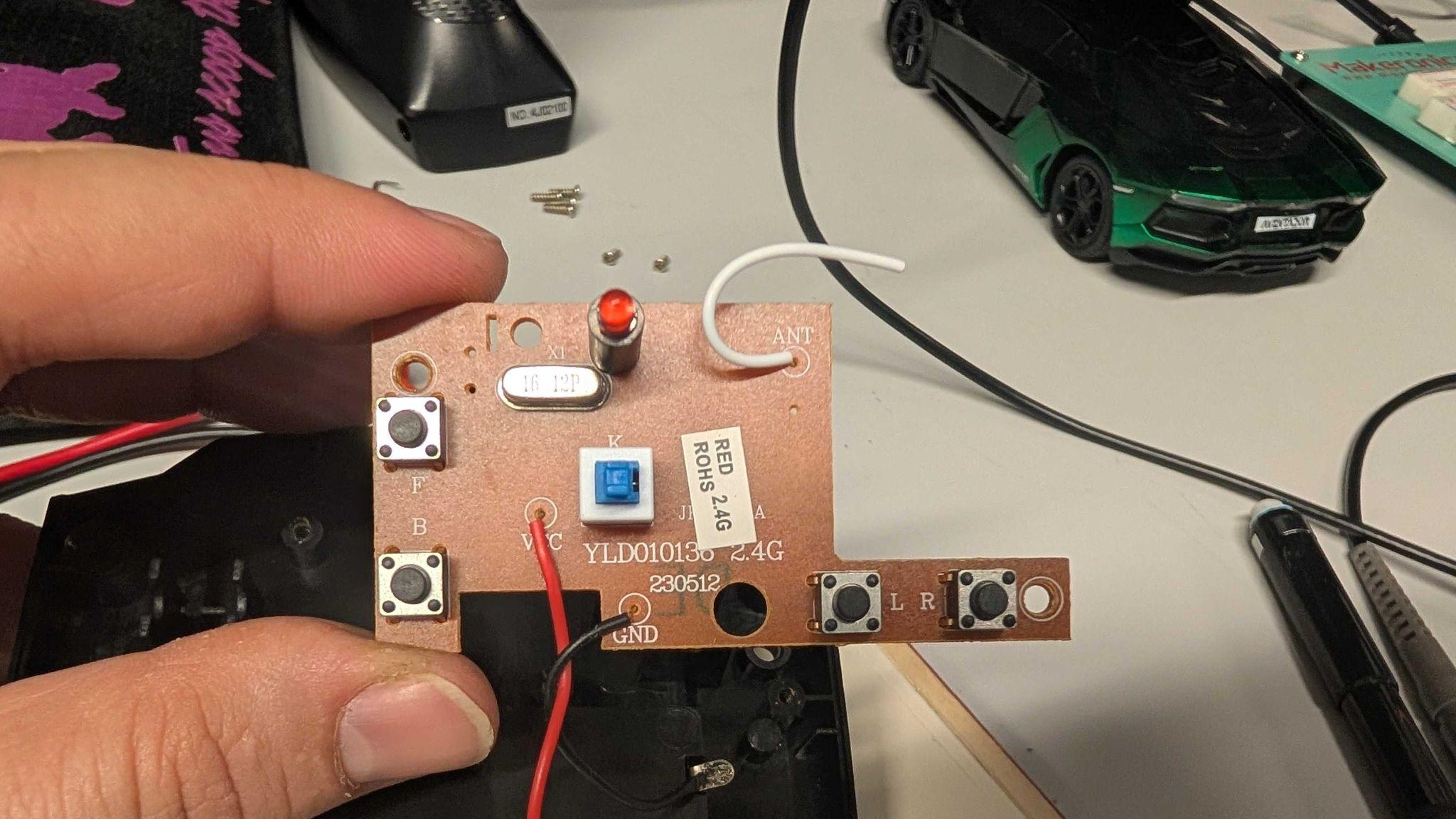
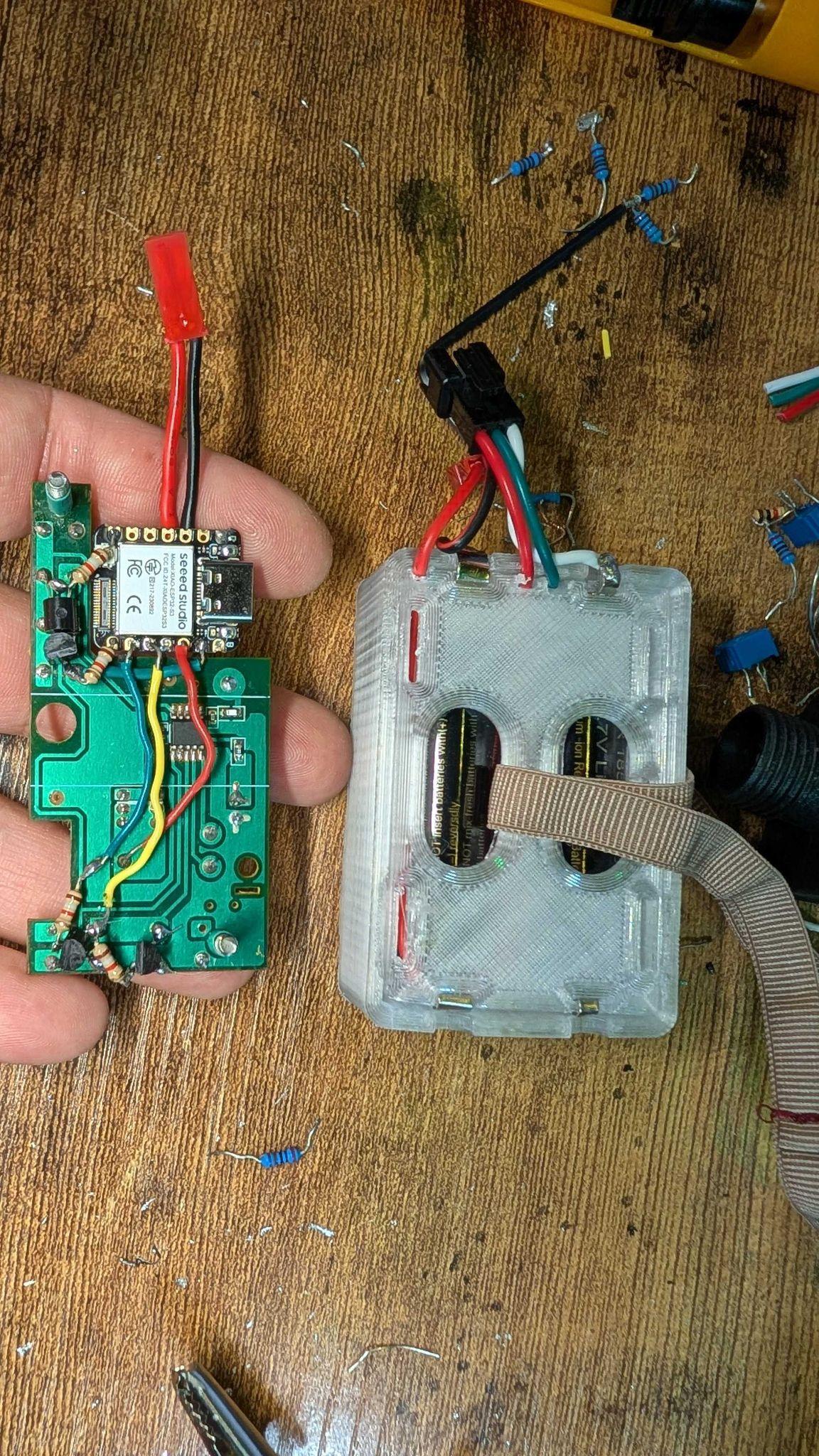
The Hack
The RC car’s transmitter uses momentary push buttons — one each for forward, back, left, right. 2N3904 NPN bipolar junction transistors were soldered directly across each button’s contacts. Each transistor’s base connects through a 1.8kΩ resistor to an ESP32S3 I/O pin. Pull the pin high → transistor saturates → button is “pressed” → car moves.
EMG-to-Action Mapping
| EMG State | Action | Pin |
|---|---|---|
| Throttle muscle active | Forward | D9 HIGH |
| Left muscle only | Turn left | D7 HIGH |
| Right muscle only | Turn right | D6 HIGH |
| Left + Right both active | Reverse | D8 HIGH |
| All inactive | Stop | All LOW |
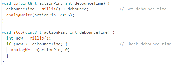
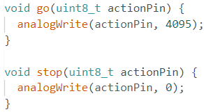
// Code
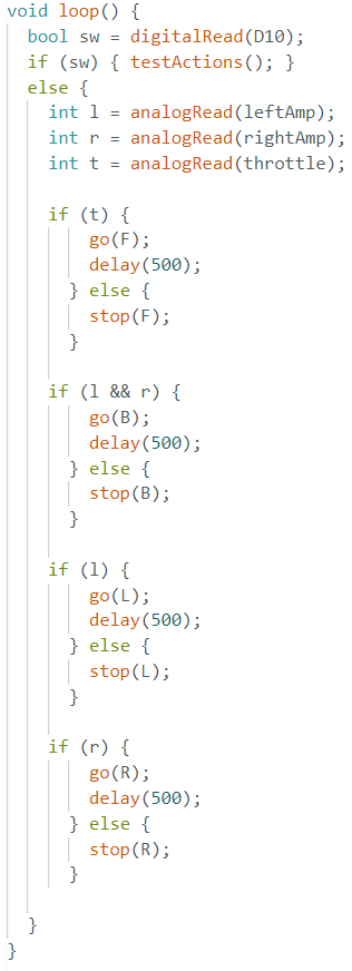
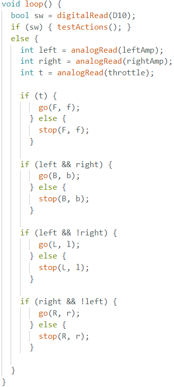
It Works!
This is so very silly. Enjoy. We sure did.
Oscilloscope Verification
Each stage was tested with a 5mVpp sine wave at 200Hz before connecting real electrodes. Every node in the chain was verified on the oscilloscope against expected gain, filtering, and waveform transformation.
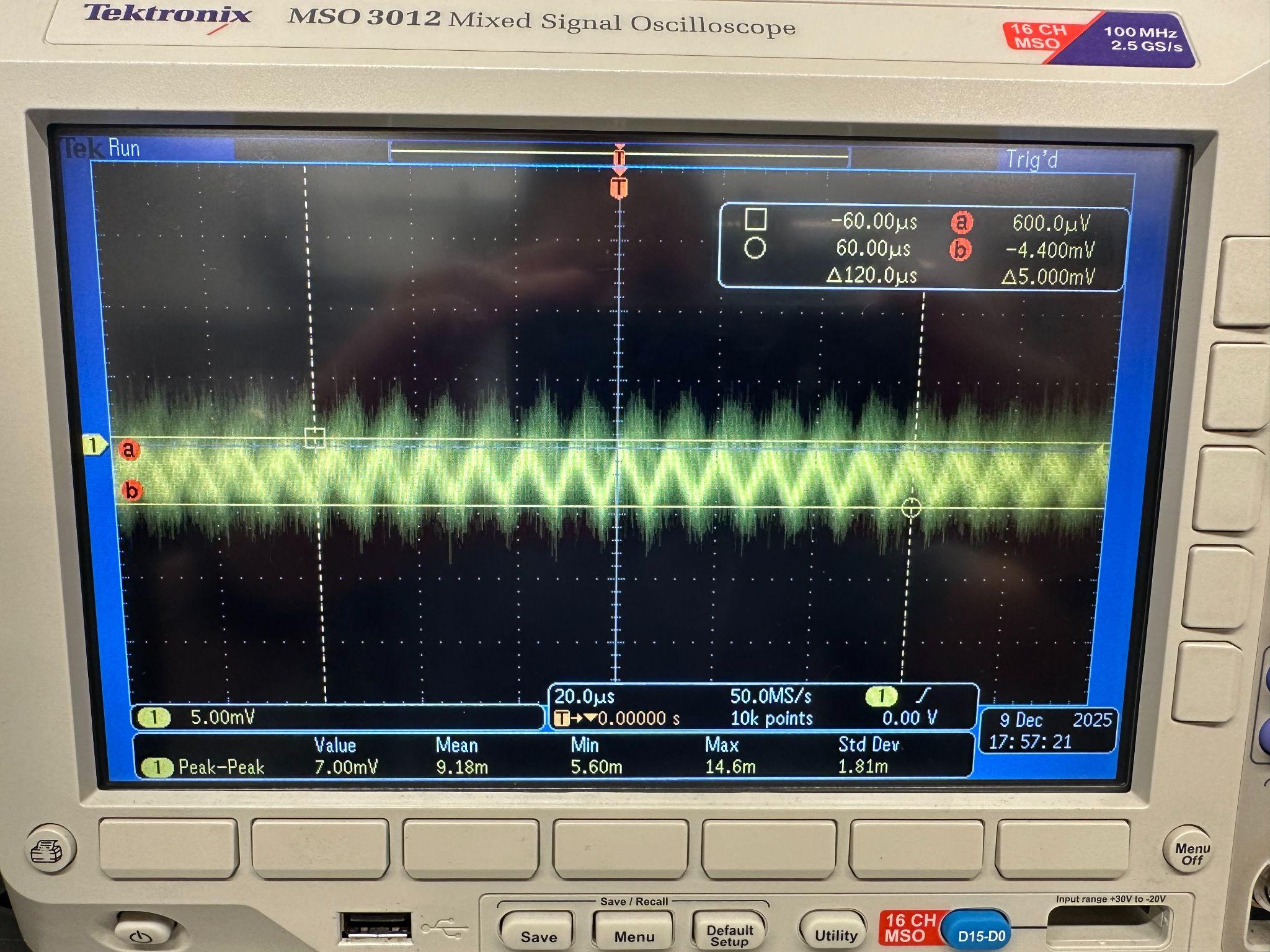
// Input Signal — 5mVpp at 200Hz
Representative muscle signal amplitude before any processing.
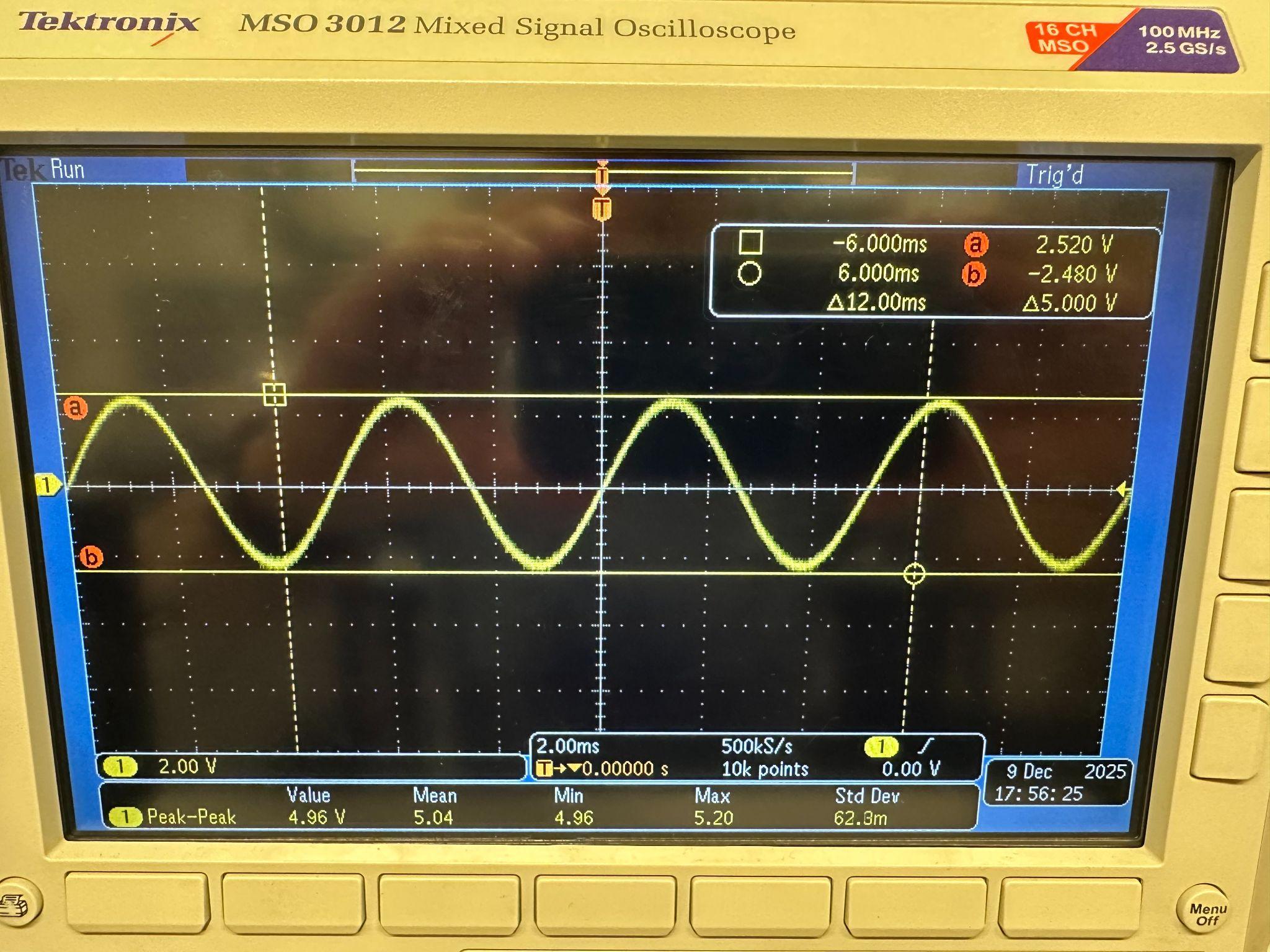
// After Instr. Amp — 5Vpp
Gain of exactly 1000 confirmed. 5mV in, 5V out.
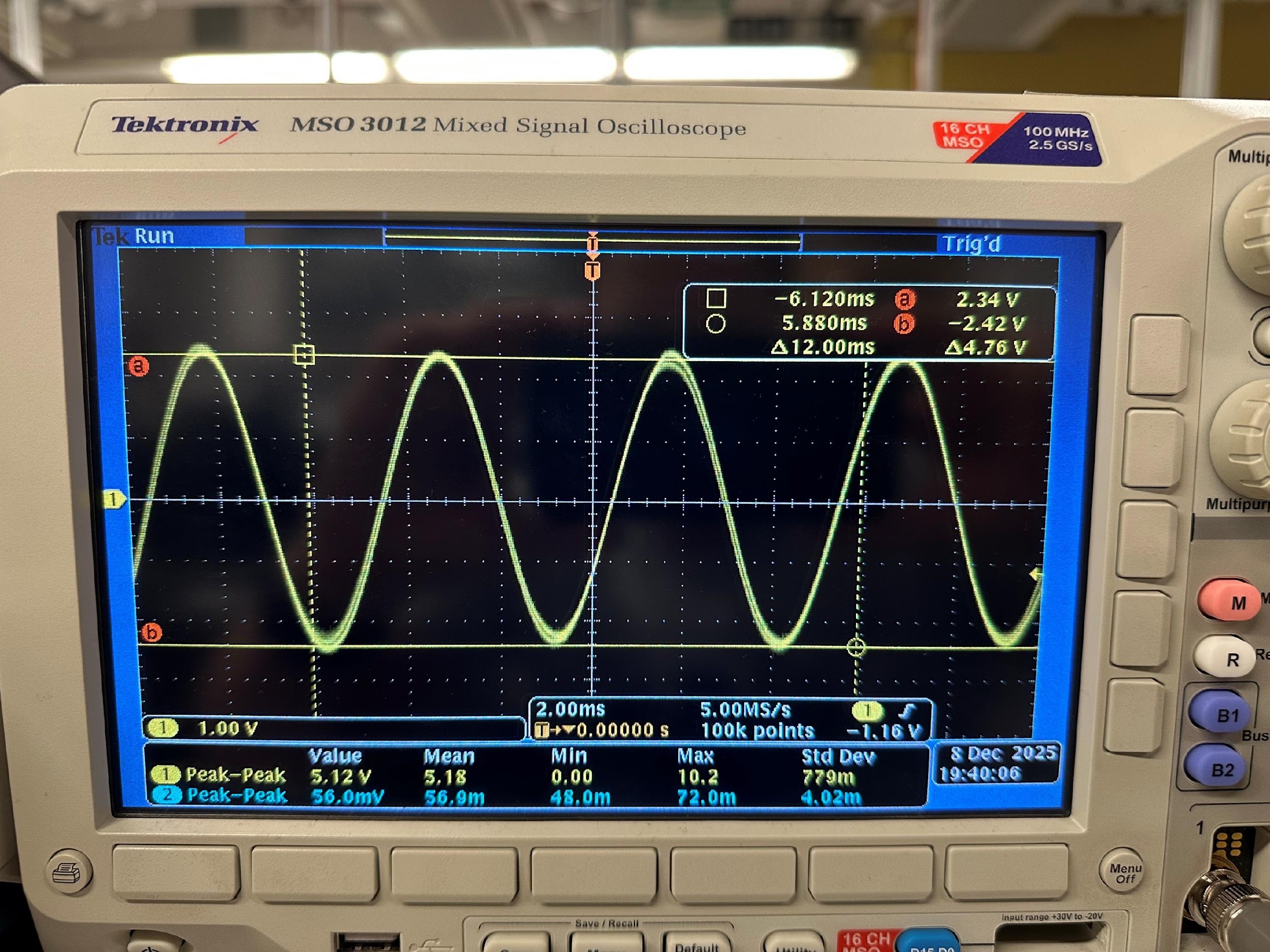
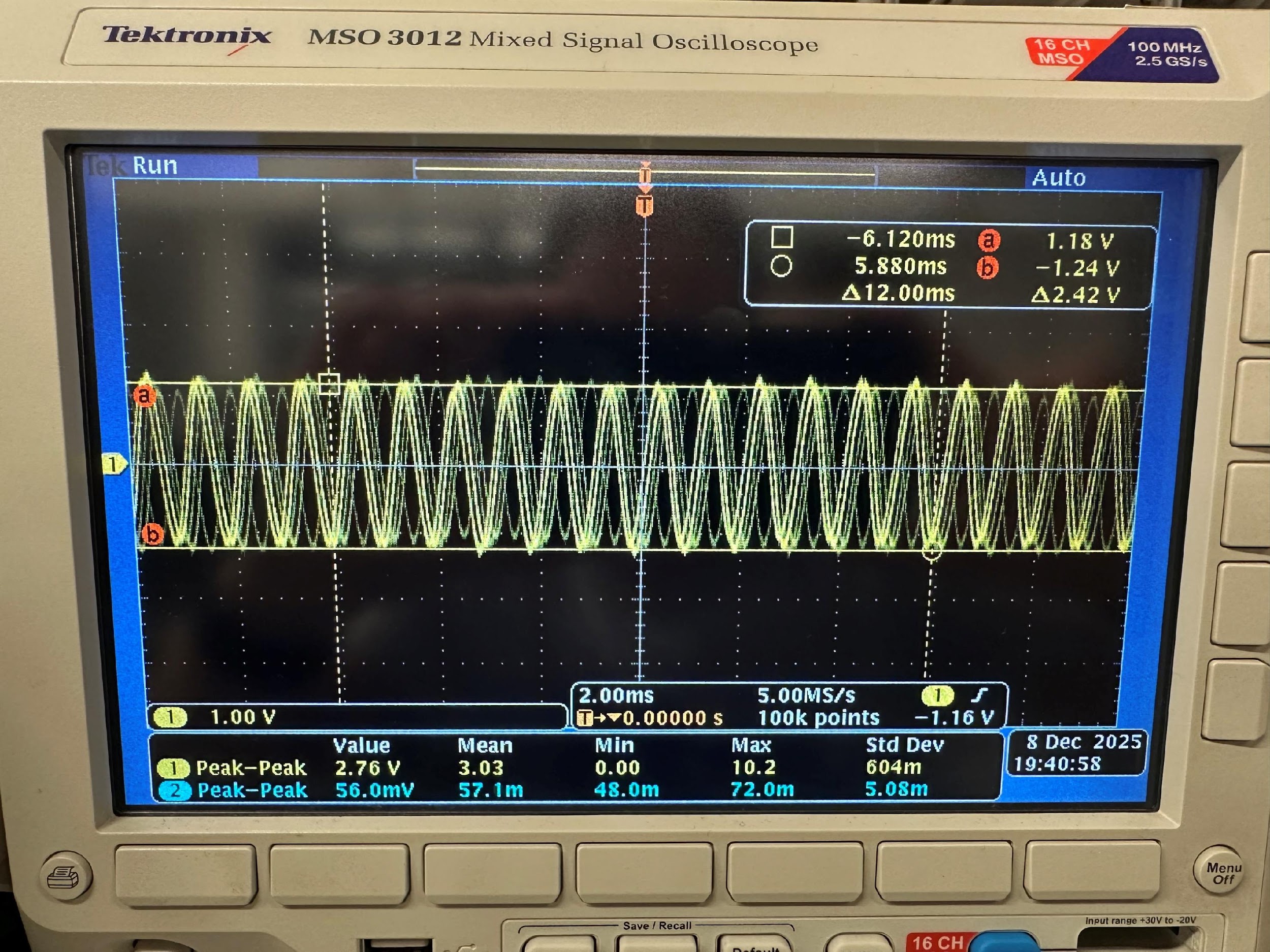
// BPF — 5.12Vpp at 200Hz (in-band)
Signal passes cleanly through the 10–500Hz window. Unity gain confirmed.
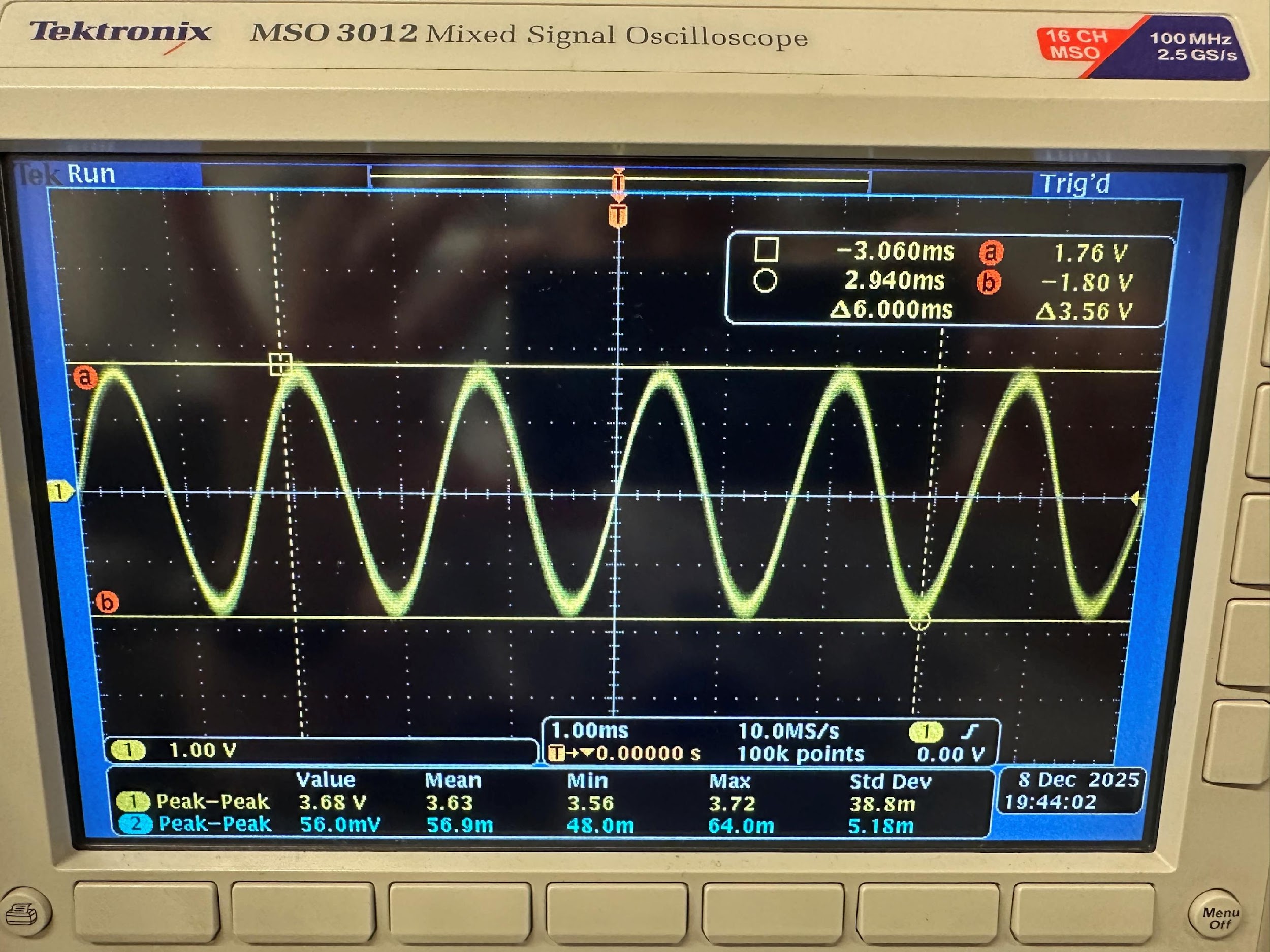
// BPF — 3.56Vpp at 600Hz
Near the high cutoff. Attenuation slower than theoretical −40dB/decade, likely due to loading from the rectifier stage.
// BPF — 2.42Vpp at 1kHz
Well above cutoff. Measured 2.42Vpp vs. theoretical 0.9Vpp.
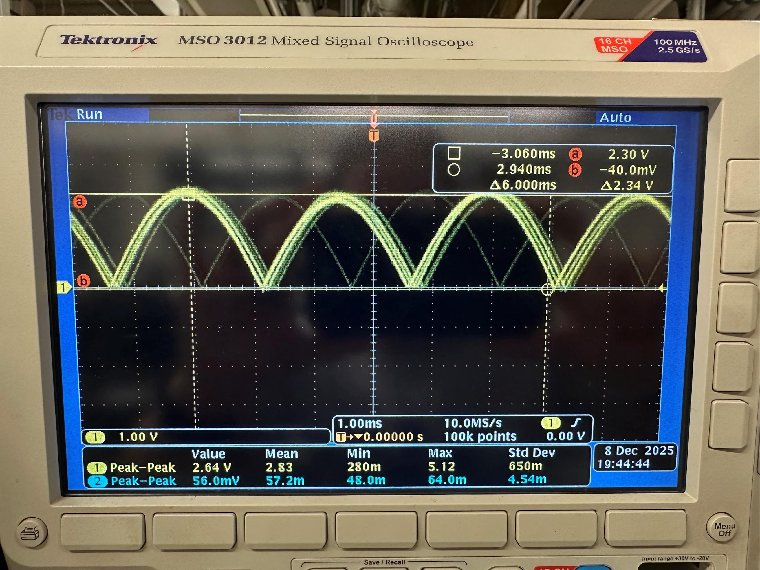
// After Rectifier — 2.34V
Bipolar sine wave folded to unipolar. All signal energy now positive.
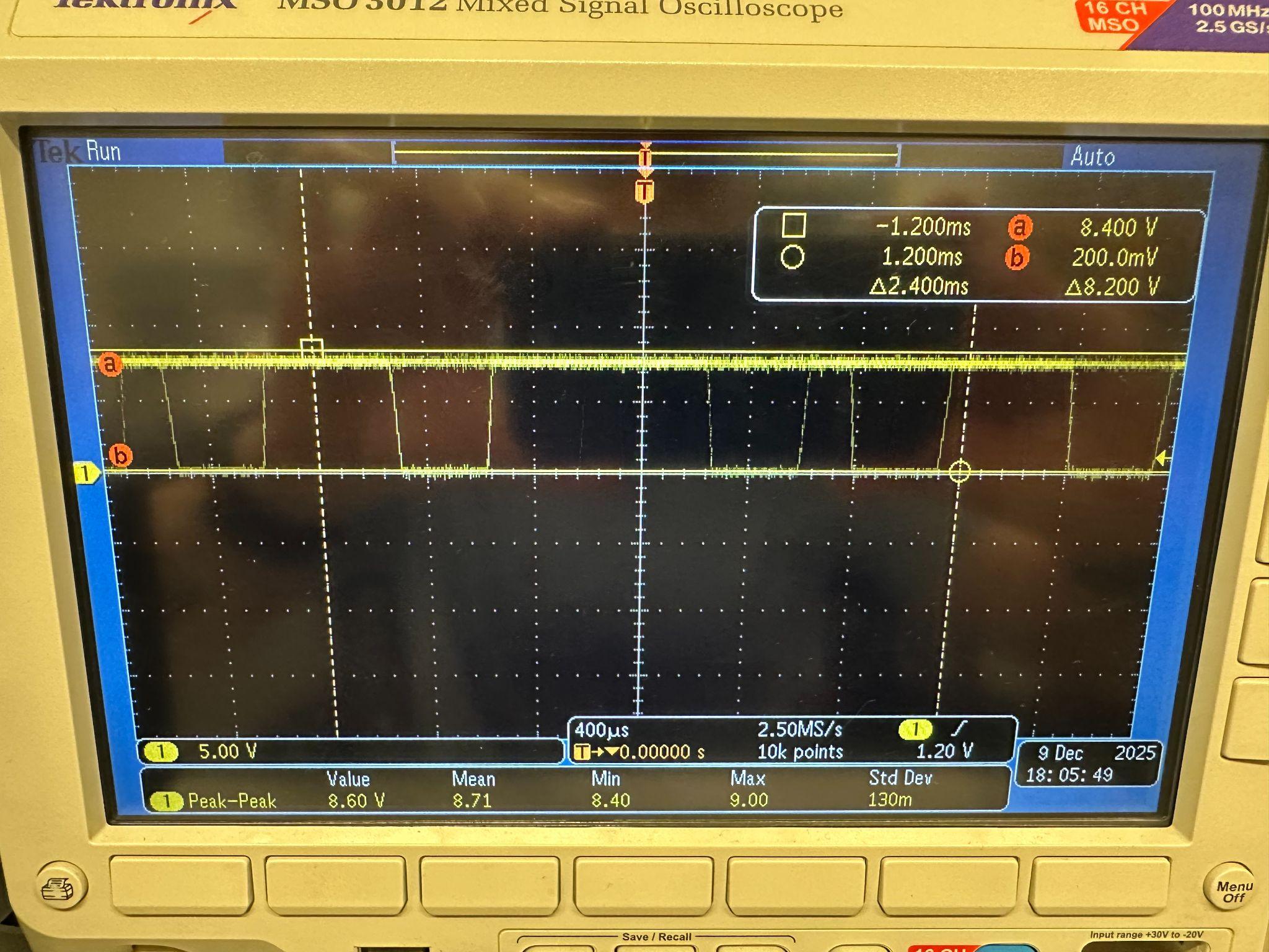
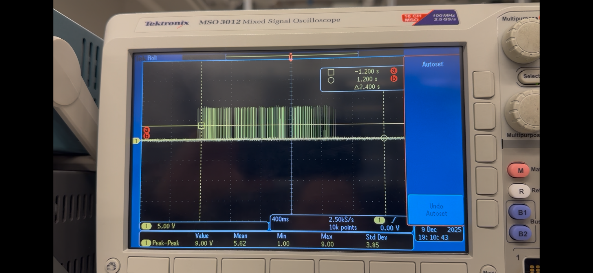
// After Comparator — 8.2V Square Wave
Clean binary trigger output. High when muscle fires, low otherwise.
// After Voltage Divider — 3.7V
Stepped down into the ESP32S3’s 0–4.2V range. Complete analog chain verified end-to-end.
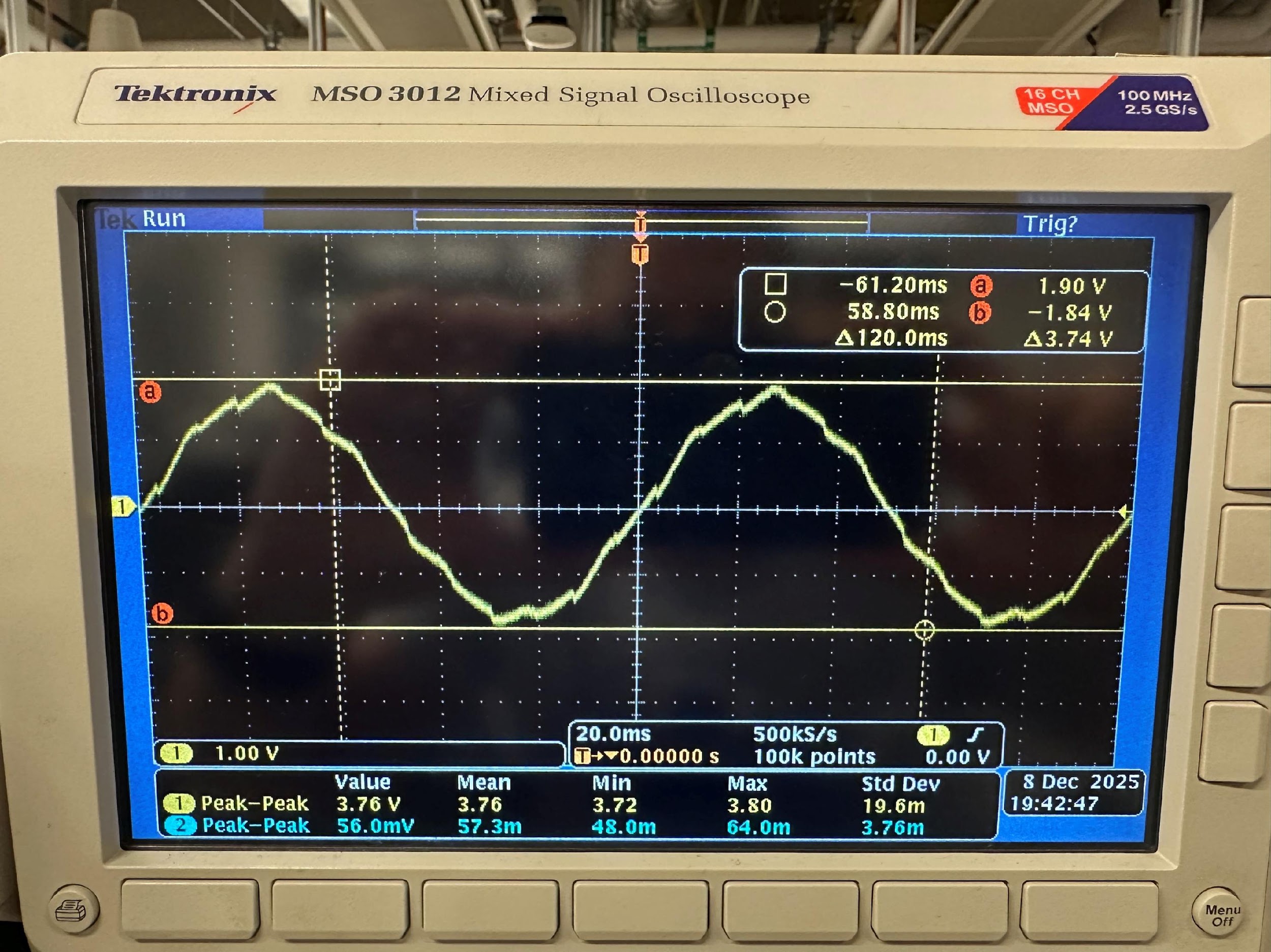
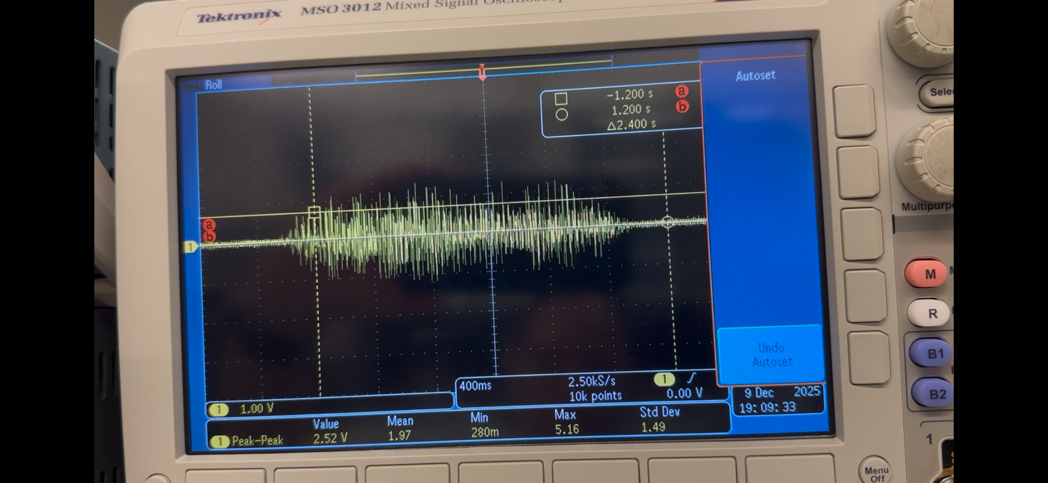
// Real EMG Signal Through the Chain
Oscilloscope captures of an actual arm flex propagating through the processing stages.
From Breadboard to Board
Once the full analog chain was verified working end-to-end on a breadboard, it was transferred to a soldered circuit board for robustness.
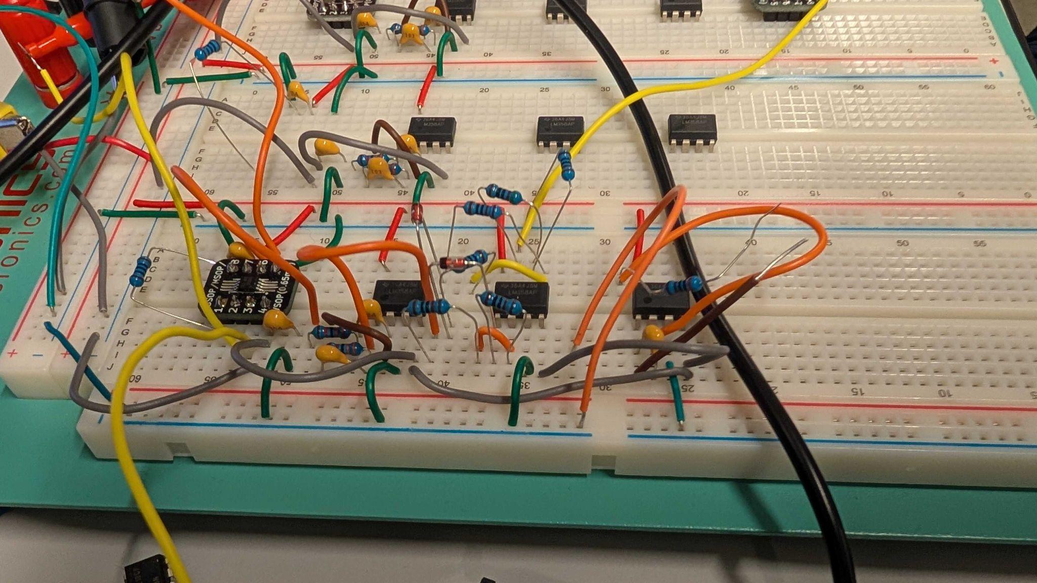
// Breadboard Prototype
Working but not pretty. Breadboarding to perfection before soldering saved considerable unsoldering time later.
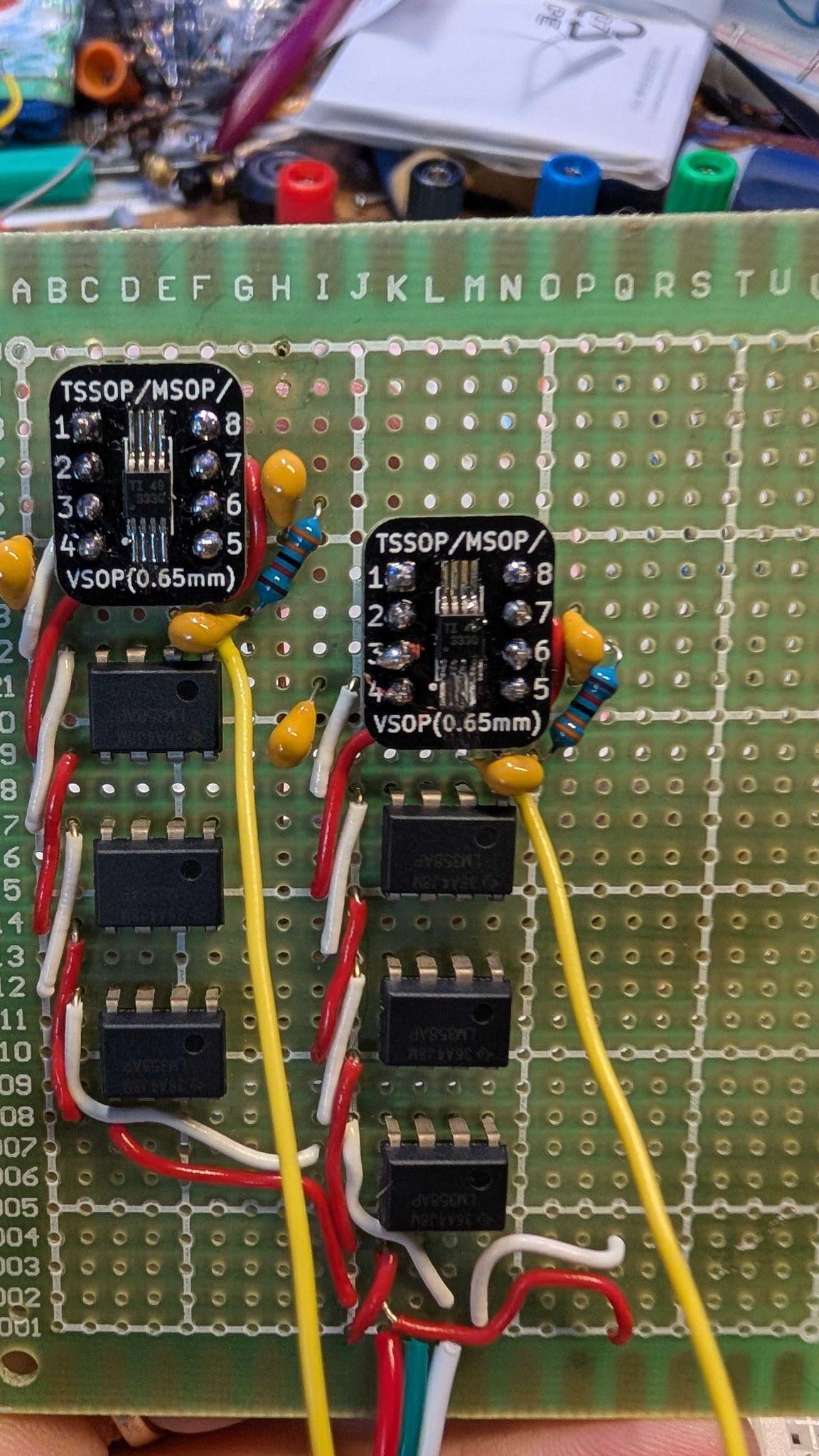
// Pretty But Not Working
The first soldered board. Tidy, but not yet functional. Troubleshooting a soldered circuit is significantly less fun than troubleshooting a breadboard. Lessons were learned.
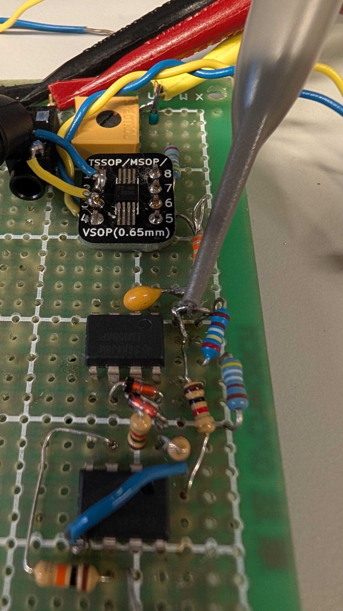
// Working Soldered Circuit
The final board with INA333 IC. Transferred from breadboard once the full chain was verified working end-to-end.
What We Learned
// Discrete vs. IC Amps
A three op-amp instrumentation amp from LM358s works just as well as the INA333, but an IC so small requires pick-and-place assembly to avoid failures.
// Rectifier Iterations
Diode bridges don’t work single-ended. The two op-amp precision rectifier works, but mind the pull-down resistors! They’ll introduce a DC offset and cost you an afternoon.
// Loading Effects
Connecting the band-pass output to the high-impedance rectifier stage altered effective component values and slowed the filter’s rolloff. Stage impedance matching matters.
// Lab Equipment
Familiarity with the oscilloscope and function generator is essential. Faulty equipment creates red-herring faults. Verify your tools before debugging your circuit.
// Breadboard Discipline
Breadboard to perfection before soldering. Tidy wiring saves troubleshooting time. Every shortcut becomes an unsoldering session later.
// EMG Is Fiddly
Electrode placement relative to the muscle really matters. Signal strength varies between people and sessions. Expect to re-tune threshold and placement every time.